
Cooling Tower and Condenser Water Design Part 7: Staging Cooling Towers and Chillers
/By Chad Edmondson
Want to make sure the cooling towers in the systems you design operate as intended? If you are a design engineer, you are responsible for outlining the staging sequences of the cooling tower systems you design. You are the only one with the expertise and the knowledge about these specific towers to get the done job right.
Before the controls contractor or controls vendor can program the system, he or she needs a list of the acceptable operational sequences from you, outlining what every piece of equipment will be doing at each and every stage.
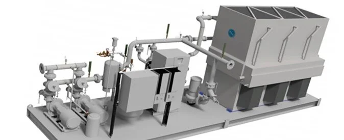
How do you develop such a list? Let’s work through an example using design details of the system shown in Figure 1.
Figure 1

Here we have (3) 500 ton cooling towers with a design flow of 1500 GPM each. Because you are the design engineer you happen to know that you have wisely selected these cooling towers for a 50% turndown, or a minimum flow of 750 GPM. The cooling towers include Weir dams, so you also know you are protected from dry air disease even at these low flow conditions. (If either of the two previous sentences confuses you, refer to Part 5: Maintaining Minimum and Maximum Flows). Remember, one of your responsibilities in creating a staging sequence is to make sure that the flow from the chillers is distributed among the cooling towers within their acceptable range. In this case, our total flow range can be anywhere from 900 GPM (dictated by the smallest chiller) all the way up to 3900 GPM, (1500 GPM + 1500 GPM + 900 GPM).
Let’s start with the least demand, wintertime conditions where we would only need our smallest chiller operating. Notice that in Chart 1 we indicate that at this stage we have our 300 ton chiller on along with Pump 1, while the other two 500 ton chillers and associated pumps are off. We’ve also indicated the flow, 900 GPM, which is well above our minimum cooling tower flow of 750 GPM. Finally, we’ve noted that both Tower 1 valves are open, while the other towers’ valves remain closed.
This represents the minimum operating condition for our condenser water loop. From here, we add each additional stage of capacity, the next of which would be with Chiller 2 operating and flow split between Cooling Towers 1 and 2, at 750 GPM each. (It is also acceptable to run a single cooling tower at this particular condition, but typically operating two cooling towers at 750 will be more efficient that operating one cooling tower at 1500 GPM).
Chart 1

We continue to work through each possible operational scenario from the lowest flow/demand condition all the way up to the highest flow/demand condition, which is with all three chillers and cooling towers operating at total flow of 3900 GPM and 1300 Tons of cooling. Notice that at this peak demand condition we are still slightly below the total flow capacity of each cooling tower so there is no danger of overflowing the equipment.
Once you complete your list of possible operating sequences for the chillers and cooling towers, you hand it over to the control contractor or vendor and he or she will develop a flow chart that looks something like this:

This is, of course, a visual representation of the programming that they (not you!) will do for the enduser. However, they will have based this on the sequencing stages that you, the engineer, have given them because you know the minimum and maximum flow conditions for the cooling towers – they don’t.
For more information, please view our video series on Cooling tower and Condenser Water Piping Design.
